0 90 Ohm Fuel Gauge Wiring Diagram
Its suppose to be between 0 and 90 ohms. I changed the gauges in my 64 and the fuel gauge is a 0 - 90 ohm gauge which reads wrong.
Diagram Moeller Fuel Tank Sending Unit Diagram Full Version Hd Quality Unit Diagram Artdiagram Amicideidisabilionlus It
Alright guys I need some help.

0 90 ohm fuel gauge wiring diagram. Complete installation instructions included knowledge of automotive wiring preferred. So I got out the meter and tested the sender. 36 angular degrees.
It is a new type of floatless fuel sender from Classic Instruments. If any other sender type is required connect a Radio Shack 275-1556 or equivalent momentary switch to the black and brown wires see illustration above or alternately touch the stripped ends of the black and brown wires. To use this gauge with the stock Smiths sender we have to apply the inverse sum math discussed above to determine the value of the resistor needed in parallel to the sending unit.
Ohm meter to the sender wire that you took off of the gauge. Always disconnect battery ground before making any electrical connections. The tank is all but full and I read 37 ohms at the sender pin on the tank to ground today.
The gauge ships pre-programmed to read GM 0-90 ohm senders. Parts of the Fuel Level Sender Unit to be Ad Fuel Level Sender Installation. Measure the depth of your fuel tank.
The unit can be adjusted to read accurately in tanks from 6 to 23 deep. Mounting holes provided and must be mounted inside of vehicle away from moisture dirt and high heat. The gauge is pegged past full.
The easiest way to get a close reading is by soldering a 47 OHM 1 watt resistor between the fuel gauge output terminal of the sender and the metal base of the sender - it will sweep pretty normally. VDO Lever arm sender 0 - 90 Ohm USA. Empty 90 Ohms the Smiths unit will give us 250-Ohms.
0-90 ohms and the less popular 0-180 ohms. I would first check your wiring from the guage to the trunk. Sender must be mounted perpendicular not at an angle from the top of the tank.
If you find you have the correct ohm range fuel sender make sure that the float arm is. I took the 0-90 ohms as a workable range for all gauges falling in that ohm range. Sensor signal input fuel level gauge.
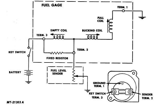
This will give you your reading at current fuel level. The sender and gauge must be matched 0-90 ohms to check tank wiring pull sender to gauge wire off senderdash gauge should show fullhold sender wire to earth and gauge should drop to emptyif it dosnt drop gauge is faulty or wire is touching body. The gauge must be the same type otherwise with a 0-90 gauge on a 240-33 sender the pointer would go backwards.
Available in 240-33 0-90 ohm resistance ranges. Dummy me that would be too easy huh. Example a tank of fuel with a 090 ohm sender would equal close to 45 ohms.
Look at continuity and resistance should be very low. Works with Fuel Safe Fuel Gauge GA2641 and all 0-90 fuel gauges. So the project begins make a conversion from the resistance type fuel senders for a voltage based display gauge The goals are.
The fuel gauge should now show the correct fuel level in the tank. The flange options are either SAE 5 hole US or screw in European 125 BSP thread. Simply wires in-line between your fuel gauge and sender no need to drop the fuel tank and change sending units.
The first step would be to make sure that you have the proper ohm range fuel sender to match your gauges. I now know the sender ohms and the gauge ohms are different therefore the gauge is not going to work right. So I finally set about figuring it out.
Hirschmann 8 pins MQS connector. Check the wiring diagram that comes with the kit and mark the back of the new fuel gauge with symbols for each post. Full 0 Ohms we cant change that so lets focus on lowering the upper value for empty.
My fuel gauge has been all kinds of flaky lately. Grounded the wire going to the fuel sender and the gauge leds dropped to empty and blink. Float Styel Fuel Level Sending Unit 0-90 ohm.
Empty 02 volts full 42 volts The sender sends in ohms. Chevrolet Fuel Gauge Operation with Resistors replacing the Sending Unit. Standard SAE 5 hole mounting pattern.
I recently put in a new 20 gallon RCI fuel Cell with a 0-90 ohm sender in my 57 Burb. S for the sender G or for the ground and I for the ignition. For example a 73-10 ohm fuel sender would read backwards on a 0-90 ohm fuel gauge.
Resistance range for an aftermarket fuel gauge might be 0-Ohms Full to 90-Ohms Empty. Well in trying to locate a sender that would work I stumbled across a possible fix for the old 90 ohm sender to a 30 ohm gas gauge. It will read EMPTY before it really is but this is a good thing because you will always have reserve fuel in the tank - Thanks Dave.
Connect the negative of the ohm meter to ground. E -12 - F. Install the new gauge reconnect the wiring and turn on the power.
If using a 0-90 ohm GM sender separately insulate the ends of the brown and black wires with electrical tape and coil them up under the dash. Empty 0 ohms full 90 ohms. Fuel Gauge.
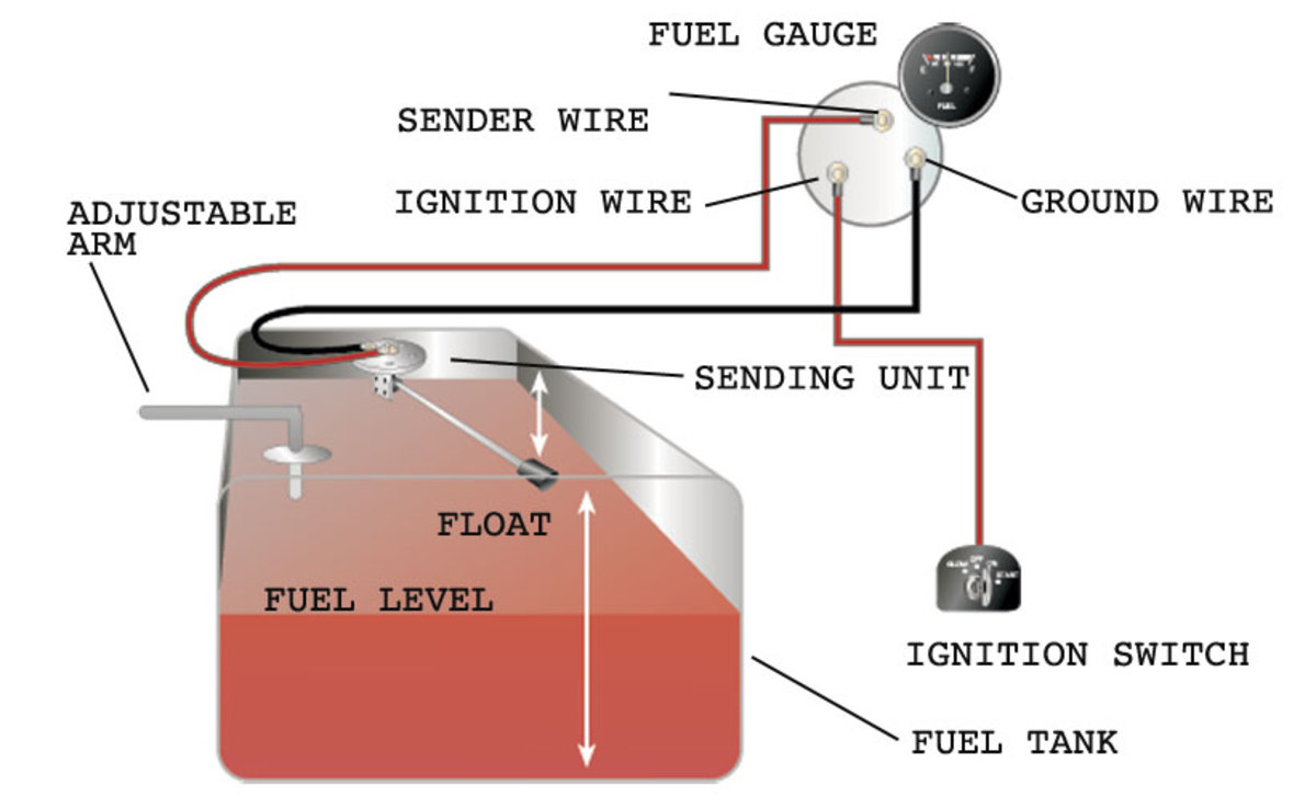
Remove wire from ground and gauge goes to full so the gauge was working just fine. Fuel level measurement range. The guage looks at resistance to ground through the sending unit in the range of 0-90 ohms.
Refer to the VDO catalog for matching fuel gauges. A pegged full guage is an indication of either NO ground infinite resistance or VERY high 90 ohms resistance. If you get an open circuit.
If you have an original GM Advanced Design sender and gauge cluster it will be 0-30 ohms and the only. This fuel level sender is designed to work in vented tanks with depths greater than 6-12 inches. Gauge requires input of Volts.
Wiring Diagram For An Electric Fuel Pump And Relay Aamidis Blogspot Com

Autometer Sport Comp Ii 52mm 73 10 Ohms Short Seeep Electronic Fuel Level Gauge In 2021 Autometer Gauges Mustang Parts Ford Mustang Parts

Amazing Sunpro Super Tach 2 Wiring Diagram California In 2021 Wiring Diagram Wiring Diagram Electrical Tachometer

Diagram Wiring Diagram For Boat Fuel Gauge Full Version Hd Quality Fuel Gauge Dmdiagram Amicideidisabilionlus It

Pioneer Radio Wiring Diagram Best Cheap Hotels Booking Deals Get Special Promo Deals Hotels Cheap Discounted Up Pioneer Car Stereo Pioneer Radio Wiring Diagram

Diagram Auto Ammeter Wiring Diagram Full Version Hd Quality Wiring Diagram Diagrammar Prolococusanese It

Diagram Harley Dyna Fuel Gauge Wiring Diagram Full Version Hd Quality Wiring Diagram Trudiagram Amicideidisabilionlus It

How To Test And Replace Your Fuel Gauge And Sending Unit Sail Magazine

Fuel Gauge To Fuel Cell Sending Unit Honda Tech Honda Forum Discussion

Ctcarid 2a 52mm Fuel Level Gauge 3 4 Ef Fuel Tank Meters 0 190ohm Waterproof With 7 Colors Backlight 932v For Motocycle Yacht Fuel Gas Yacht Boat Marine Boat

Digital 20fuel 20fitting 20instructions 201 2013 By Howard Instruments Issuu

Diagram Cj2a Fuel Gauge Wiring Diagram Full Version Hd Quality Wiring Diagram Veediagram Amicideidisabilionlus It

Diagram Rpm Gauge Wire Diagram Full Version Hd Quality Wire Diagram Buydiagram Segretariatosocialelatina It

How To Test And Replace Your Fuel Gauge And Sending Unit Sail Magazine

Autometer Z Series 85mm 120 Mph Speedometer Mechanical Gauge Gauges Auto Mechanic

Kus Marine Tachometer Gauge Led Hourmeter Boat Rpm Tachometer 12v 24v 8000rpm Tachometer Boat Engine Outboard

Allway Instrument Speedometer Cluster Lcd Screen Display For Mercedes Benz W203 C230 C240 C320 C Class 2001 2004 Check Mercedes Benz W203 Mercedes C Class


