09 Maxxforce Voltage Gauge Wiring Diagram
Describe the meaning of the G-W in diagram component R. When testing bi-metal type gauges it is also necessary to check the operation of the instrument voltage stabiliser.
Diagram 99 Altima Wiring Diagram Full Version Hd Quality Wiring Diagram Diagrammoi Prolococusanese It
It shows the parts of the circuit as simplified shapes and the power as well as signal links between the devices.

09 maxxforce voltage gauge wiring diagram. Low voltage disconnect b1 c1 spfm01f1 frcf52_b f52a1-08 hb2 d a72a4 fm01c10-130 fm01f1-130 note. Spade on back of gauge. A wiring diagram is a simplified standard pictorial depiction of an electrical circuit.
Describe the meaning of the dotted line in the diagram component P. MAZDA WIRING DIAGRAMS WORKSHEET 1 1. The MaxxForce 9 and 10 jet can be identified by a knurled area at the base of the tube.
They are basically the same. Describe the meaning of the SD in diagram component T. The 2010 MaxxForce 9 and 10 jets are identical however the DT jet is unique.
The fuel gauge should now show the correct fuel level in. 09 1 2 1 110 wiring diagram index name description page. Maxxforce Cummins and Isuzu engines Diagnostic and electrical.
The MaxxForce 9 and 10 jet is matched to a shorter connecting rod and steel piston. Describe the meaning of the C13 in the diagram component Q. - The fuel strainer can be seen when the pump is removed from the filter module.
16 2007 MaxxForce DT 9 10. Be sure that body or mounting flange of sender is grounded to suitable chassis ground. SensorMAP The MAP sensor is a variable capacitance sensor that is used to detect the intake manifold boost pressure.
If there is none- this guide is not for you. As stated earlier the traces in a Monaco Rv Wiring Diagram represents wires. Power supply circuit protection 14 wiring diagram.
Aa batt ign dr acc 141 batt ign 141 acc ulvd ulvd f56 5a fuse. Also when measuring current that exceeds 10A which can be handled with the internal one. For bi-metal type regulator connect a 12 volt test lamp between output terminal of stabiliser and ground.
Describe and identify the diagram component Q. Gauges and warning lights fuel filter restriction and water in fuel lights p975 gauges and warning lights park brake light and transmission oil temp. Describe and identify the F in diagram component S.
Fuel sending unit wiring diagram volovetsfo. You need a wiring diagram with an external shunt instead. At that point you might have to get it running and then start wiggling wires all over unit you find the bad spot and the engine shuts down.
Kenworth Wiring Diagram Pdf kenworth t800 wiring diagram pdf kenworth w900 wiring diagram pdf kenworth wiring diagram pdf Every electrical structure consists of various unique components. Reconnect negative - battery cable. If not the arrangement wont work as it should be.
Describe the meaning of the 2 in diagram component S. I have been looking for the wiring diagram for fuel gauge but for some reason no luck on my resources. Describe and identify the diagram component U.
Im working on a 2001 mack ch612 I have power to the brake light switch located on the fire wall in the cab it is two wire I have 12 volts to the. If no lvd connectors b1 and c1 are plugged together. Describe and identify the RB in diagram component R.
But coloring of wires vary. The MaxxForce DT jet is matched to a longer DT connecting rod and aluminum piston. There is a connector with thick wires and connector with thin wires.
Check all your ignition related fuses in the side electrical hatch to make sure everything is ok and not corroded. S08322 3200 4100-4400 7300-7500 85008600 RXT Models Built March 1 2007 to March 18 2008 Electrical Circuit Diagrams. Injunction of two wires is generally indicated by black dot in the junction of two lines.
UNDERSTANDING TOYOTA WIRING DIAGRAMS WORKSHEET 1 1. 2010 MaxxForce DT 9 and 10 Engine Diagnostic Manual Navistar N9 N10 Diagnostic Manual DESCRIPTION - EPA 2010 and later DT 9 10 engines use a fuel module that incorporates many features including an electric fuel pump fuel heater and fuel strainer. MaxxForce DT 9 10 2010 - 2013 Engine Wiring Diagram Page 2 of 3 86-Pin Connector 6341 53-Pin Connector 6340 Twisted pair Red B Battery Voltage Red High side driver control Blue VREF 5 Volts Green Green AC Speed Signal Signal Brown Data Communication Black Black Purple Injectors GND Ground Low side driver control Color code for schematic lines.
Set adjustment knob to required values as detailed on chart see below. Connect ground wire from ground post on gauge to suitable chassis ground. Occasionally the wires will cross.
S08332 CF 500 600 Starting September 1 2007. SensorEOT The EOT sensor is a twowire thermistor sensor used to measure engine oil temperature. But it doesnt imply connection between the cables.
Holidays and all. S08339 ProStar and LoneStar Built January 2007 to June 2010. ELECTRONIC CONTROL SYSTEM DIAGNOSTICS WARNING To prevent personal injury or death read all safety instructions in the Safety Information Air Management System Lube System Fuel System Timing System MAXXFORCE 11 and 13 R section of Engine Diagnostics Manual EGES- Air Control Valve Beginning with 2010 Model.
Each component ought to be set and connected with other parts in specific way. Describe and identify the diagram component T. Connect wire from ignition switch to the positive I terminal on the back of gauge.
Voltage above normal or shorted to high source 23 2023 Gauge Cluster 4 Fault on Analog Input 4 below when used for ambient light Voltage below normal or shorted to low source 23 2023 Gauge Cluster 11 Message ignition and switched ignition do not match. Root cause not known 23 2023 Gauge Cluster 12 Failure of non-volatile memory or checksum fault.

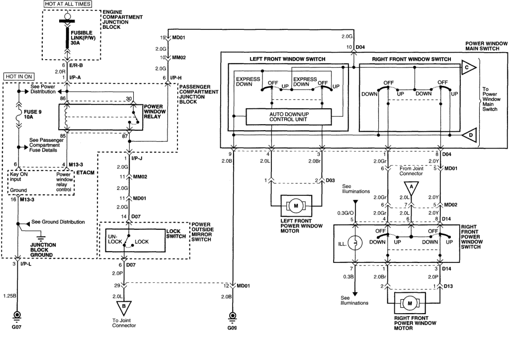
Diagram 2004 Hyundai Santa Fe Window Wiring Diagram Full Version Hd Quality Wiring Diagram Diagramrt Teatrodelloppresso It

Diagram 64 Gto Wiring Diagram Full Version Hd Quality Wiring Diagram Snadiagram Segretariatosocialelatina It

Peugeot 206 Wiring Diagram Download Free Peugeot 206 Wiring Diagram Pdf This Peugeot 206 Wiring Diagram Covered Info Wiring Diagram Peugeot Warning Lights

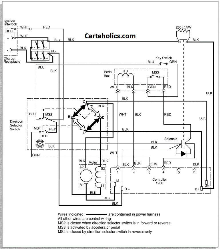
Diagram E Z Golf Wiring Diagram Full Version Hd Quality Wiring Diagram Imdiagram Segretariatosocialelatina It
International Maxxforce Diagrama Naturaleza Energia Y Recursos

Diagram Home Ac Wiring Diagram Full Version Hd Quality Wiring Diagram Diagramman Prolococusanese It

Unique Electrical Schematics Diagram Wiringdiagram Diagramming Diagramm Visuals Visualisation Graphical Wiring Diagram Diagram Freightliner
International Maxxforce Diagrama Naturaleza Energia Y Recursos

Diagram Yamaha Gas Wiring Diagram Full Version Hd Quality Wiring Diagram Diagramman Prolococusanese It
Diagram Gmc C8500 Wiring Diagram Full Version Hd Quality Wiring Diagram Diagramman Prolococusanese It
Diagram 2004 Chevy Trailblazer Blower Motor Wiring Diagram Free Picture Full Version Hd Quality Free Picture Buydiagram Segretariatosocialelatina It

Diagram 10base T Wiring Diagram Full Version Hd Quality Wiring Diagram Imdiagram Segretariatosocialelatina It

Diagram X 13 Motor Wiring Diagram Full Version Hd Quality Wiring Diagram Diagramman Prolococusanese It
Diagram Headlamp Wiring Diagram Full Version Hd Quality Wiring Diagram Imdiagram Segretariatosocialelatina It

Diagram 72 Thinline Wiring Diagram Full Version Hd Quality Wiring Diagram Adiagrams Nordest4x4 It

Wiring Diagram Trailer Light Wiring Electrical Diagram

Diagram 2006 Lincoln Navigator Wiring Diagram Full Version Hd Quality Wiring Diagram Diagrammd Prolococusanese It
2013 Maxxforce Dt 9 10 Wiring Diagrams Electronics Engines
Diagram Auto Repair Wiring Diagrams Full Version Hd Quality Wiring Diagrams Diagramman Prolococusanese It


