1960s Wiring Diagram Effects Pedal
Boss ac2 acousticsimulator schematic 276 KB boss bd 2 blues driver pedal schematic 155 KB boss bd2 bluesdriver schematic 155 KB boss bf 2 flanger pedal schematic 97 KB boss bf2 flanger schematic 102 KB. Updated - a remotefootswitch bypassing system now includes updated layouts and wiring diagrams.

Perf And Pcb Effects Layouts Fender Fender Electronic Circuit Design Diy Guitar Pedal
ES-335 Prewired Standard Assembly P-GMOD-6.

1960s wiring diagram effects pedal. Effects pedal order can be a pretty confusing subject at first. Hello I am trying to build the gaspedal dumbbell pedal with the dual effects offboard wiring diagram. Nov 23 2012 - This Pin was discovered by Colt Jackson.
First one focus on the PlexDrive and the second one in the JCM side of the JCM Drive since the JTM side is close to the PlexDrive. Discover and save your own Pins on Pinterest. Stompbox Guitar Pedal Wiring Diagram Guitar pedals Diy guitar pedal Electronics projects diy.
Each wiring diagram is shown with a treble bleed modification a 220k resistor in parallel with a 470pF cap added to the volume pots. The voltage value of capacitors does not have serious influence on the system as well as resistors wattage value neither does but considering that effects are 9 12 or 18 V circuits try to use the lower voltage caps. Fortunately there is a method to the madness when it comes to arranging your pedals.
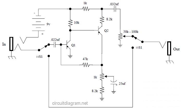
Is the pedal main input it goes to hot tip of the input audio jack. At the end of the second part Im testing both pedals stacked together. 1 There is no wire connecting the ground at the top of circuit 2.
We have 64 Boss Diagrams Schematics or Service Manuals to choose from all free to download. With the True double bypass two effects loop runningThis can easily two or more units without effect True Bypass and effects in the running. Weve already connected the ground to the circuit board from the second foot-switch.
This controls the ON-OFF of the status LED. 800 x 600 px source. AMZ is a resource with information about diy guitar effects pedals stompboxes audio circuits and tips on how to build them.
Here are some of the leading illustrations we obtain from different resources we wish these photos will certainly work to you and also hopefully really appropriate to just what you want concerning the Guitar Effects Schematics Diagrams is. There are fuzzbox schematics signal booster projects audio mixers and much more available free. It doesnt matter how you do it just as long as one ground wire goes to that second circuit board and to.
11699 - revision 2 - added bounding pot to diodes for more control over diode distortion. We dont need it. We created several and we have redrawn some schematics that were already available on the internet for readability or ease of use these needed an easier-to-read format corrections or part identifiers.
Boss Od-1 Overdrive Guitar Pedal Schematic Diagram size. A-B-Y switch With the A-B-Y switch can be either a signal to 2 individual outputs switch AB or 2 outputs simultaneously set YThe first counter A B switches between the outputs A and B the second switch Y the input signal to both outputs. And how you add the block determines the structure of your tone.
Ive prepared a couple of videos demoing these two exciting pedals. A germaniumsilicon transistor hybrid Fuzz Face that screams. Please select your desired model below.
As you can see this is a little more complex than the single footswitch version but its still a very simple build that shouldnt take you long to get working. Its best to imagine each effect as blocks. 14 W resistors will go fine also.
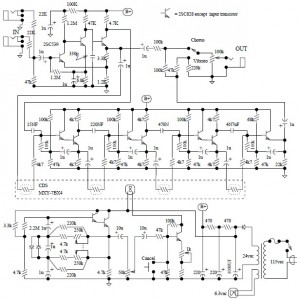
Stephan Moellers AC 30 simulator circuit. This is my first pedal so Im a tad nervous about it. Worth noting that putting a volume pedal before drives will greatly reduce the gain as well as the volume of the drive pedals when the volume pedal is between 0 and 100.
Vox sfbasspa schematic 159 KB vox solid state pa 50 sspa50 50w amplifier late 1960s schematic 326 KB vox solid state pa 50 sspa50 50w amplifier late 1960s schematic 325 KB vox solid state pa 100 amplifier late 1960s schematic 206 KB vox solid state pa 100 amplifier late 1960s schematic 205 KB. People also love these ideas. Its ready to build.
As you add a pedal you are adding a new block to your tower of sound. Are these separate boards from the main board or are they the same or different boards entirely because I. Below is a wiring diagram of how these components fit together and what the pedal will look like in the enclosure once youve finished it.
But in the diagram it shows each pot going to a vero board so heres the question. Bypass up to six effects from a remote footswitch. Here is a list of the schematics that are exclusive to this site.
Take some time to browse the site and discover information that can help you with your next DIY effects pedal project. Basically it takes it to Ground when the switch is engaged closing the LED circuit and turning it on. Now with tonevolume controls toner patterns wiring diagrams and commentary on building the boards.
Connect your neck pickup to the pigtail labeled N and your bridge pickup to the pigtail labeled B. Many of these schematics include modernization that are included and explained. 4 Small Lengths of Wire.
Goes to the effect PCB input the pad called IN on the effect board. If the volume pedal is placed after drives in the chain it will only affect the volume so that way you would get a fully overdriven signal but at a lower volume as opposed to a low volume AND low gain signal if its placed before drives. 112899 - to reduce some of the brightness of the pedal you may want to put a capacitor 001uF - 01uF in parallel with the clipping diodes.

Perf And Pcb Effects Layouts Lovepedal Super 6 Layout Electronic Circuit Design Simple Circuit
Electrical Wiring Pleasant Diy Guitar Pedal Projects Offboard Soldering Along Distortion Plus Wiring Diy Guitar Pedal Diy Guitar Pedal Projects Guitar Pedals

Flatearthguitars Com Fender Vintage Guitar Building Wiring Diagram
Univibe Pedal Electronic Schematic Diagram

Wiring Diagram Brian May Guitar

Perf And Pcb Effects Layouts 64 Vox Tone Diy Guitar Pedal Diy Guitar Amp Guitar Pedals

Pin On Pedalkimana

Perf And Pcb Effects Layouts Optical Bypass Electronics Mini Projects Electronics Projects Diy Guitar Pedals

Perf And Pcb Effects Layouts Vibrato Diy Guitar Pedal Guitar Pedals Direct Boxes

Stompbox Guitar Pedal Wiring Diagram Guitar Pedals Diy Guitar Pedal Guitar Diy

Perf And Pcb Effects Layouts Deadastronaut Tremshifter Electronics Mini Projects Diy Guitar Pedal Merry Christmas Eve Eve

Mod Garage Three Ways To Wire A Tone Pot Guitar Pickups Guitar Diy Cigar Box Guitar Plans

3pdt Wiring Dpdt Wiring 3pdt Switch Dc Jack Led Guitar Pedal Switching 3pdt Switch No Dc Jack Led Gui Guitar Pedals Diy Guitar Pedal Wiring Diagram
Vox Tone Bender Pedal Electronic Schematic Diagram

Vox Vintage Circuit Diagrams

Boss Nf 1 Noise Gate Pedal Schematic Diagram Electronics Basics Noise Guitar Pedals

A Generic Stompbox Wiring Diagram Tonefiend Com Wiring Diagram Simple Circuit Electronic Circuit Projects
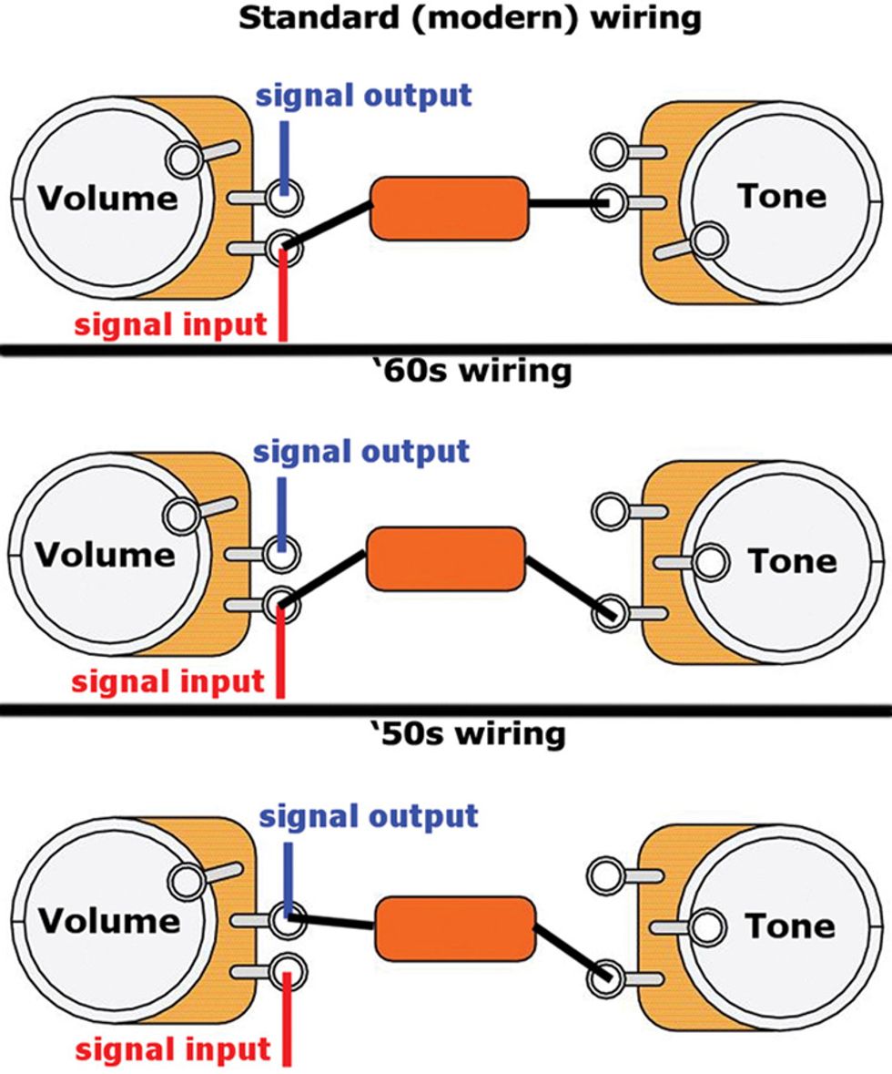
Mod Garage Three Ways To Wire A Tone Pot Premier Guitar

Diagram 1960 Pontiac Wiring Diagram Full Version Hd Quality Wiring Diagram Diagramman Prolococusanese It