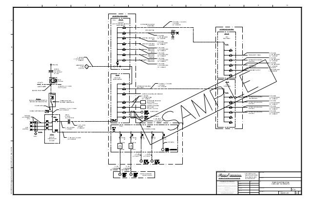
1734-top Wiring Diagram
That the wiring base assembly is one of the following. Allows the mounting base to be removed and replaced as necessary without removing any wiring.

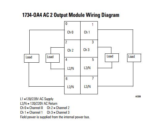
Point I O Input Module
10 Module wiring diagram Description Description 1 Module locking mechanism 5 Interlocking side pieces 2 Slide-in writable label 6 Mechanical keying 3 Handle 7 DIN rail locking screw orange 4 1734-TOP or 1734-TOPS one-piece terminal base with screw or spring clamp 8 Module wiring diagram.

1734-top wiring diagram. Activities including installation adjustments putting into service use assembly disassembly and maintenance are required to be carried out by suitably trained personnel in accordance with applicable code of. 8 POINT IO 4 Channel High Density Current Input Module Publication 1734-IN032D-EN-P - August 2016 Install the Mounting Base To install the mounting base on the DIN rail Allen-Bradley part number 199-DR1. 0 1 2 3 Mechanical keying orange Module wiring diagram Module locking.
Users are required to familiarize themselves with installation and wiring instructions in addition to requirements of all applicable codes laws and standards. POINT IO Wiring Base Assembly Installation Instructions publication 1734-IN013 Provides installation information about 1734-TB3 and 1734-TB3S assemblies POINT IO One-piece Wiring Base Assembly Installation Instructions publication 1734-IN028 Provides installation information about 1734-TOP 1734-TOPS 1734-TOP3 and 1734-TOP3S assemblies. Allen-Bradley ControlLogix and POINT IO are trademarks of Rockwell Automation.
To reinsert the removable terminal block proceed as follows. 1734-TOP 1734-TOPS 1 9 8 7 6 2 4 5 44221 3. 1734-TOP 638 g 225 oz 1734-TOP3 792 g 279 oz 1734-TOPS 5568 g 196 oz 1734-TOP3S 668 g 236 oz Wire Size 02525 mm2 2214 AWG solid or stranded copper wire rated at 75 C.
Motorcycle Contact Point Wiring Diagram Diagram Base Website. The wiring base consists of a base and a removable terminal block RTB. The examples and diagrams in this manual are included solely for illustrative Faults at the door interlock switch wiring terminals or safety controller will be detected The IB8S input module monitors two door channels and two lock.
Insert the end opposite the handle into the base unit. This end has a curved section that engages with the wiring base. 5V Maximum load current 150ma Terminal Base Assemblies and RTBs 1734-TOP screw-clamp or 1734-TOPS spring-clamp A POINT IO one-piece mounting base which includes integrated terminal locations.
1734-TB 1734-TBS POINT IO Removable Terminal Block Installation. Self-Configuring modules are also available to reducesimplify your design and your inventory. 1734-TB or 1734-TBS POINT IO two-piece terminal base which includes the 1734-RTB removable terminal block and 1734-MB mounting base 1734-TOP or 1734-TOPS POINT IO one-piece terminal base Module Status Network Status NODE.
Publication 1734-SG001F-EN-P - September 2015. 0 1 2 3 Mechanical keying orange Module wiring diagram Module locking. Wiring diagram DIN rail locking screw orange Mechanical keying Interlocking side pieces Slide-in writable label Handle 1734-TOP or 1734-TOPS one-piece terminal base with screw or spring clamp 45712 Modules Mounted on 1734-TOP or 1734-TOPS One-piece Terminal Base.
0 1 2 3 Mechanical keying orange Module wiring diagram Module locking. Solved 1734 Top Catalog Block Autodesk Community Autocad. The pulse test outputs of the IB8S can if not used for pulse testing.
The POINT IO module B snaps into the base. 1734-TB or 1734-TBS POINT IO two-piece terminal base which includes the 1734-RTB removable terminal block and 1734-MB mounting base 1734-TOP or 1734-TOPS POINT IO one-piece terminal base Module Status Network Status NODE. 1734 Ib8s Point Guard I O Input Module 8 Inputs 24 V Dc.
1734-TBS 1734-TB3S 1734-RTBS 1734-RTB3S POINT IO Removable Terminal Block Installation. Use a bladed screwdriver to rotate the keyswitch on the mounting base clockwise until the number required for the type of module being installed aligns with the notch in the base. 1734-TB or 1734-TBS POINT IO two-piece terminal base which includes the 1734-RTB removable terminal block and 1734-MB mounting base 1734-TOP or 1734-TOPS POINT IO one-piece terminal base Module Status Network Status NODE.
This manual is a reference guide for the AENTR AENTR Series B. On 4753 Allen Bradley 1769 Plc Wiring Diagrams Also Allen Bradley. The POINT IO System.
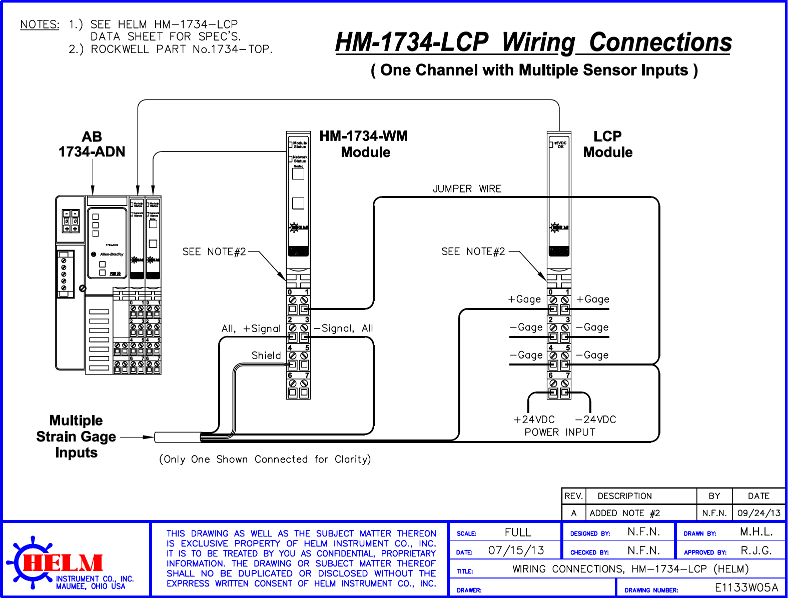
Dimensions HxWxD approx 49 x 12 x 144 mm 193 x 047 x 567 in 1734-TOP 1734-TOPS 49 x 12 x 168 mm 193 x 047 x 661 in 1734-TOP3 1734-TOP3S Weight approx 638 g 225 oz 1734-TOP. Refer to wiring diagram E1133W05A in Appendix A. 2Slide the wiring base down allowing the.
1734-TOP 1734-TOPS 1734-TOP3 1734-TOP3S POINT IO. 1734-TOP 1734-TOPS 49 x 12 x 144 mm 193 x 047 x 567 in 1734-TOP3 1734-TOP3S 49 x 12 x 168 mm 193 x 047 x 661 in Weight Approx. The examples and diagrams in this manual are included solely for illustrative Allen-Bradley Rockwell Automation ArmorPOINT ControlLogix Logix.
The 1734-TBS uses spring-clamp terminations. Run jumper wire from HM1734-WM - gage to - gage terminal of LCP module. Make certain the DIN-rail locking screw is in the horizontal position.
Installing the Wiring Base 1Position wiring base vertically above installed units interface power supply or existing module. The 1734-TB uses screw-clamp terminations. 4 Handle 9 Module wiring diagram.
Allen Bradley 1734-aentr Wiring Diagram. The base A mounts onto the DIN rail and provides the backplane. 1734-TOP Base Follow these steps to install the module.
That the wiring base assembly is one of the following. 668 g 236 oz 1734-TOP3S. 792 g 279 oz 1734-TOP3 5568 g 196 oz 1734-TOPS.
That the wiring base assembly is one of the following.
Proccontsite

Diagram Lennox Pulse Wiring Diagram Full Version Hd Quality Wiring Diagram Diagramman Prolococusanese It
Allen Bradley 1734 Ob4 1734 0b4 Modul Output Seri C Fw 3 022

Pin On All Used Cars

18 2012 Camry Electrical Wiring Diagram Wiring Diagram Wiringg Net Electrical Wiring Diagram Types Of Electrical Wiring Electrical Wiring

Diagram I O Card Wiring Diagram Full Version Hd Quality Wiring Diagram Snadiagram Segretariatosocialelatina It

Air Conditioner Wiring Diagram Pdf Window Ac Csr Carrier Split Ac Wiring Electrical Circuit Diagram Ac Capacitor

Home Theater Speaker Wiring Diagram Wiring Diagram Access Control System Security Camera Wiring Diagram

Peugeot Wiring Diagram 206 Wiring Diagrams All Peugeot Wiring Diagram Engine Diagram

15 Basic Engine Wiring Diagram Engine Diagram Wiringg Net Volvo Wiring Diagram Alternator

George Sampson 1732 1734 Bank Of England Bank Of England London Eth Zurich Prof A Caruso Archive Re Eth Zurich Reference Architecture Drawing
Hdi Wiring Instructionsdsd Screw Switch


How To Wire In A Starer Button On Glow Plugs On A 7 3 Idi In 2021 Wiring Diagram Diagram Relay
Diagram Yamaha L2 Wiring Diagram Full Version Hd Quality Wiring Diagram Diagramman Prolococusanese It


Proccontsite

17 Honda Motorcycle Electrical Diagram Motorcycle Diagram Wiringg Net Electrical Wiring Diagram Electrical Diagram Motorcycle Design

Helix Shop Manual Wiring Diagram Diagram Free Gas
Star Delta Control Connection Diagram Engineers Commonroom Delta Connection Delta Electrical Engineering Projects
Hm1734 Lcpplm R1 Lcp Manual